Understanding Valve Guide Replacement
Heart valve procedures, like the Ross procedure or TAVR, address faulty valves, sometimes requiring replacement with bioprosthetic options lasting 10-15 years.
What are Valve Guides?
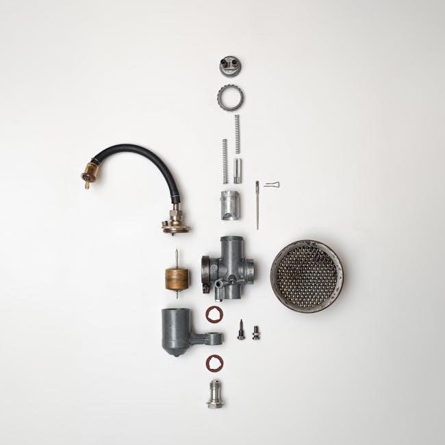
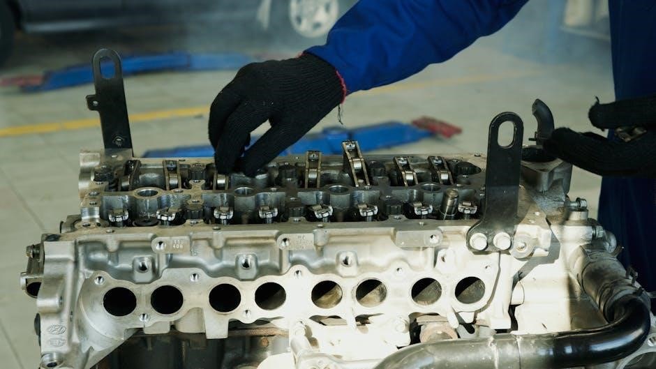
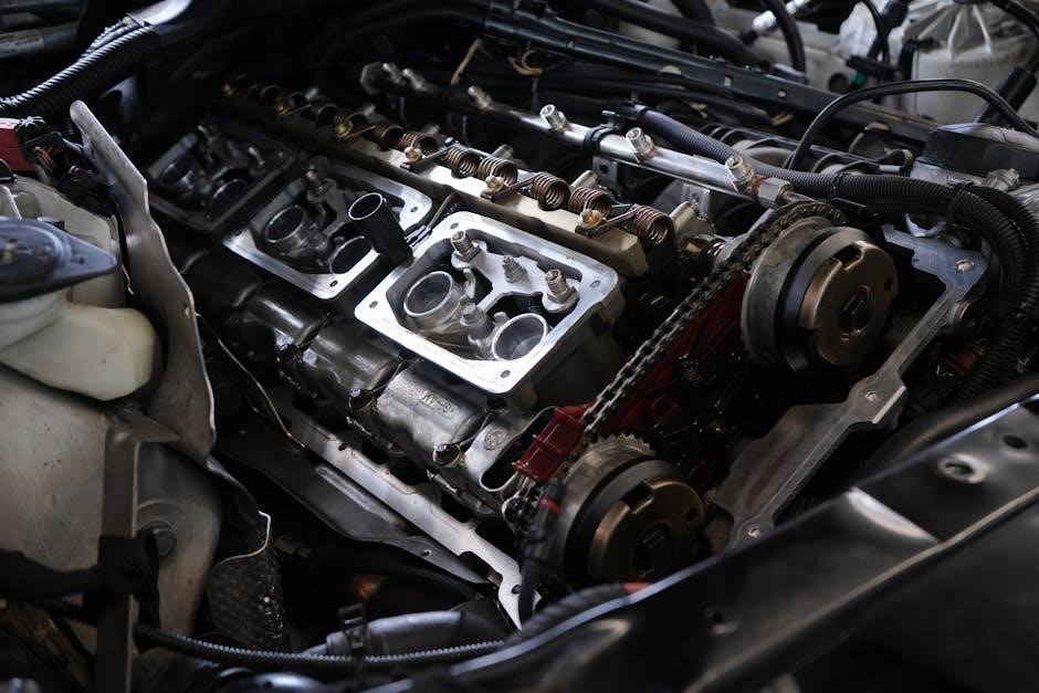
Valve guides are crucial cylindrical components within an internal combustion engine, precisely positioned within the cylinder head. Their primary function is to maintain the correct alignment of the engine valves as they move up and down during the engine’s operating cycle. These guides are typically manufactured from durable materials like cast iron, bronze, or chilled iron, chosen for their wear resistance and ability to withstand the high temperatures and stresses inherent in engine operation.
They aren’t directly involved in sealing the combustion chamber; instead, they ensure the valves travel straight, preventing them from binding or tilting. Proper valve guide function is essential for efficient combustion, optimal engine performance, and minimizing emissions. Over time, these guides can wear due to constant friction from the valve stems, leading to valve wobble and potential engine problems, necessitating replacement procedures.
The Function of Valve Guides in Engine Operation
Valve guides play a pivotal role in ensuring precise valve movement, directly impacting engine efficiency and performance. They meticulously control valve alignment during the intake and exhaust strokes, preventing valve wobble and ensuring a tight seal against the valve seats. This precise control is fundamental for maintaining optimal combustion chamber pressure and maximizing power output.
Without properly functioning valve guides, valves can deviate from their intended path, leading to incomplete combustion, reduced engine power, increased emissions, and potential valve-to-piston contact – a catastrophic engine failure. The guides’ ability to withstand high temperatures and constant friction is critical. Procedures like valve seat cutting and lapping rely on accurate guide alignment. Ultimately, their function is to facilitate the reliable and consistent operation of the entire valve train system;
Diagnosing Valve Guide Issues
Faulty heart valves necessitate diagnosis, mirroring engine issues where identifying problems is key; procedures like TAVR address valve dysfunction, requiring careful assessment.
Common Symptoms of Worn Valve Guides
Identifying worn valve guides requires recognizing specific indicators, much like diagnosing heart valve problems where symptoms dictate the course of action. While directly correlating engine valve guides to human heart valves is an analogy, the principle of malfunction leading to noticeable effects remains consistent. In engines, excessive oil consumption is a primary sign, as oil bypasses the piston rings and enters the combustion chamber due to valve stem seal failure exacerbated by guide wear.
Furthermore, noticeable blue smoke from the exhaust pipe signifies oil burning. Reduced engine performance, including a loss of power and acceleration, can also occur. Valve float, where the valve doesn’t fully close, leading to a rough idle and misfires, is another key symptom. Unusual engine noises, such as ticking or tapping sounds, may also indicate valve train issues. These symptoms, similar to recognizing complications after a heart valve procedure, necessitate a thorough inspection to pinpoint the root cause and determine the appropriate repair strategy.
Methods for Diagnosing Valve Guide Wear
Diagnosing valve guide wear involves a systematic approach, mirroring the detailed assessments used in procedures like TAVR or the Ross procedure to evaluate valve function. A visual inspection, performed during engine disassembly, is the initial step, looking for scoring or excessive wear on the valve stems and guides themselves.
Valve stem-to-guide clearance is measured using a dial indicator, determining if it exceeds the manufacturer’s specifications. A “valve float” test, observing valve movement at higher RPMs, can reveal guides unable to maintain proper valve control. Leak-down tests help identify combustion gas escaping past the valves, potentially indicating guide issues. Furthermore, specialized tools allow for precise guide bore measurement. Similar to how probes assist during heart surgery, these tools ensure accurate diagnosis. Correct identification is crucial, as it dictates whether repair or complete valve guide replacement is necessary for optimal engine performance.
Tools Used in Valve Guide Inspection
Accurate valve guide inspection demands specialized tools, much like the probes utilized during advanced heart procedures such as mitral valve replacement or the Ross procedure. Valve guide measuring tools, including internal micrometers and bore gauges, precisely determine guide inner diameter. Dial indicators, mounted to measure valve stem runout, reveal guide-to-stem clearance.
A valve spring compressor is essential for safe valve disassembly. Visual inspection benefits from a strong light source and magnification, aiding in detecting subtle wear patterns. Feeler gauges confirm stem-to-guide clearance. Digital calipers provide accurate measurements of valve stem diameter. Similar to the precision required in cardiac surgery, these tools ensure accurate assessment. Proper calibration of these instruments is vital for reliable results, guiding decisions on whether valve guide replacement is necessary to restore optimal engine performance and prevent further damage.
Valve Guide Replacement Procedure
General anesthesia, like in heart surgeries, prepares the patient; disassembly follows, mirroring valve repair or replacement, demanding precision for optimal engine function.
Preparation and Disassembly
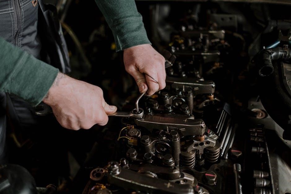
Before initiating the valve guide replacement, meticulous preparation is paramount. This begins with a comprehensive assessment of the engine’s overall condition to identify any contributing factors to valve guide wear. Thoroughly drain all fluids – coolant, oil, and fuel – to prevent contamination and ensure a clean working environment. Disassembly commences with removing components obstructing access to the cylinder head, including the intake and exhaust manifolds, valve cover, and rocker arms.
Carefully document the position of each part during removal, utilizing labeling or photographs to facilitate accurate reassembly. Once access is gained, the valve springs and retainers are removed, followed by the valves themselves. It’s crucial to handle valves with extreme care to avoid damage to the valve faces and stems. With the valves removed, the cylinder head is prepared for valve guide removal, often involving cleaning and inspection for any further damage or wear that might necessitate additional repairs.
Valve Guide Removal Techniques
Several methods exist for removing worn valve guides, each suited to different levels of wear and available tooling. The most common technique involves utilizing a valve guide driver, a specialized tool designed to push the guide out from the cylinder head’s valve seat side. Applying steady, even pressure is crucial to avoid damaging the cylinder head.
Alternatively, for severely worn or seized guides, a valve guide removal tool employing a collet-type grip can be used. This tool securely clamps onto the guide’s outer diameter, allowing for controlled extraction. In some instances, heating the cylinder head locally can aid in loosening the guide due to thermal expansion differences. Regardless of the method, careful attention must be paid to avoid damaging the valve seat area. Post-removal, the guide bore must be thoroughly cleaned and inspected for any remaining debris or imperfections.
Valve Guide Installation Methods
Proper installation of new valve guides is paramount for optimal engine performance and longevity. Typically, new guides are installed using a valve guide installation tool and a hammer. The guide is carefully aligned with the cylinder head’s valve seat bore, and the installation tool ensures a straight, even drive.
Prior to installation, the valve guides are often chilled to reduce their diameter, facilitating easier insertion. Once seated correctly, the guides are driven in until flush with the cylinder head surface. Following installation, the valve guide bores are often honed to achieve the correct internal diameter and a smooth surface finish. This honing process ensures proper valve stem-to-guide clearance. Precise measurements and adherence to manufacturer specifications are essential throughout the installation process to prevent binding or excessive play.
Selecting the Right Valve Guides
Choosing appropriate valve guides is crucial for a successful engine rebuild. Considerations include engine type, performance goals, and valve material. Options encompass cast iron, bronze, and chilled iron guides, each possessing unique characteristics. Cast iron guides are a common, cost-effective choice for standard rebuilds, while bronze guides offer superior wear resistance, particularly beneficial for high-performance applications.
Chilled iron guides represent a durable middle ground. Bioprosthetic valve longevity, mirroring guide material durability, is a key factor – some materials last longer than others. Matching the guide material to the valve stem material minimizes wear and ensures proper sealing. Always consult engine specifications and consider the operating conditions to select guides that will withstand the stresses and temperatures encountered during engine operation, ultimately maximizing valve train reliability.
Types of Valve Guides
Valve guide materials include cast iron, bronze, and chilled iron options, each offering varying durability and wear resistance for heart and engine valves.
Cast Iron Valve Guides
Cast iron valve guides represent a traditional and cost-effective choice for many engine applications, though they aren’t universally preferred due to inherent material properties. These guides are manufactured through a casting process, resulting in a relatively porous structure compared to other materials like bronze or chilled iron. This porosity can lead to increased wear over time, particularly in high-performance engines or those subjected to demanding operating conditions.
While offering adequate performance in standard engines, cast iron guides may not withstand the stresses associated with higher temperatures or increased valve spring pressures. Consequently, they often require more frequent inspection and potential replacement compared to their more durable counterparts. The material’s susceptibility to wear can contribute to valve guide recession, leading to oil consumption and reduced engine efficiency. Despite these drawbacks, their affordability makes them a viable option for certain rebuilds and restorations, especially where budget constraints are a primary concern.
Bronze Valve Guides
Bronze valve guides offer a significant upgrade over cast iron, prized for their superior wear resistance and inherent lubricating properties. The material itself contains a high percentage of copper, contributing to excellent heat dissipation and reducing the risk of valve sticking. This makes them particularly well-suited for high-performance engines and applications where consistent valve control is critical.
Unlike cast iron, bronze guides possess a tighter grain structure, minimizing porosity and enhancing durability. They exhibit lower friction against the valve stem, promoting smoother operation and extending valve life. While generally more expensive than cast iron, the increased longevity and reduced maintenance requirements often justify the investment. Bronze guides are frequently chosen during engine rebuilds aiming for improved reliability and performance, especially when addressing issues related to oil consumption or valve train noise. They represent a balance between cost and performance, making them a popular choice for a wide range of engine types.
Chilled Iron Valve Guides
Chilled iron valve guides represent a step up in durability from standard cast iron, achieved through a specialized hardening process. This process rapidly cools molten iron, creating a very hard and wear-resistant surface layer. This hardened exterior provides excellent resistance to abrasion from the valve stem, making them a robust choice for demanding engine applications.
While not as inherently lubricious as bronze, chilled iron guides offer a good compromise between cost and performance. They are significantly stronger than standard cast iron, reducing the likelihood of cracking or deformation under high temperatures and pressures. They are often selected during engine rebuilds where increased durability is desired without the higher expense of bronze. Proper installation and precise sizing are crucial with chilled iron guides, as they can be more brittle and susceptible to damage if mishandled. They provide a reliable solution for restoring valve train integrity in a variety of engine configurations.
Post-Replacement Procedures
Following valve work, procedures like valve seat cutting, lapping, and precise valve adjustment are essential for optimal engine performance and longevity, ensuring proper sealing.
Valve Seat Cutting and Lapping
After valve guide replacement, achieving a perfect seal between the valve and valve seat is paramount for efficient combustion and preventing compression loss. Valve seat cutting precisely angles the seat to match the valve face, ensuring optimal contact. This process utilizes specialized cutting tools and meticulous measurements to create a consistent sealing surface.
Subsequently, valve lapping refines this seal further. A lapping compound, a mildly abrasive paste, is applied to the valve face and seat. The valve is then rotated and pressed onto the seat, gradually smoothing any minor imperfections and creating a leak-proof barrier. This manual process demands patience and attention to detail.
Properly executed valve seat cutting and lapping are crucial for maximizing engine power, reducing emissions, and extending the lifespan of the newly installed valve guides and valves. Ignoring these steps can lead to reduced performance and potential engine damage.
Valve Adjustment
Following valve guide replacement and valve seat work, precise valve adjustment is essential to ensure correct valve timing and optimal engine performance. This process establishes the proper clearance between the valve stem and the rocker arm or camshaft follower. Incorrect valve lash – too tight or too loose – can lead to significant issues.
Too little clearance can cause valves to remain slightly open when they should be closed, resulting in compression loss and potential valve damage. Conversely, excessive clearance reduces valve lift, diminishing engine power and efficiency. Adjustment methods vary depending on engine design, utilizing shims, threaded adjusters, or rocker arm adjustments.
A meticulous approach, following the manufacturer’s specifications, is vital. Accurate valve adjustment guarantees smooth engine operation, maximizes power output, and minimizes wear on critical engine components, contributing to long-term reliability.
Engine Reassembly and Break-In
After meticulous valve adjustment, careful engine reassembly is paramount, ensuring all components are correctly installed and torqued to specification. This includes the cylinder head, valve cover, and related hardware. Utilizing new gaskets and seals is highly recommended to prevent leaks and maintain optimal compression.
The initial engine break-in period is crucial for seating the new valve guides and valves properly. This typically involves running the engine at varied speeds and loads, avoiding prolonged high-RPM operation. Oil changes are frequently performed during break-in to remove any metallic particles generated from initial wear.
Monitoring engine performance closely during this phase – checking for oil leaks, unusual noises, and proper temperature regulation – is essential. A successful break-in period establishes a solid foundation for long-term engine reliability and performance.
Potential Complications and Troubleshooting
Valve procedures, like replacements, carry risks such as blood clots or infection; proper diagnosis and preventative measures are vital for longevity and success.
Common Issues During Replacement
During valve guide replacement, several complications can arise demanding careful attention and skilled intervention. Ensuring patient stability under general anesthesia, with assisted breathing via an endotracheal tube and ventilator, is paramount. Surgeons must meticulously address potential issues like improper seating of the new guides, which can lead to continued valve wobble and diminished engine performance.
Furthermore, damage to the valve seats during removal or installation is a concern, necessitating valve seat cutting and lapping for a proper seal. Inadequate preparation or incorrect guide selection can also contribute to premature wear or failure. Maintaining strict sterile conditions is crucial to prevent infection, a risk inherent in any surgical procedure. Post-operative monitoring for blood clots and hemodynamic imbalances is also essential for a successful outcome and long-term valve function.
Preventative Measures for Valve Guide Longevity
Extending the lifespan of valve guides requires a proactive approach focused on minimizing wear and tear. Regular engine maintenance, including consistent oil changes with high-quality lubricants, is fundamental. Oil effectively reduces friction and dissipates heat, key factors in guide degradation. Avoiding prolonged periods of high-RPM operation and allowing the engine to warm up properly before demanding performance can also significantly reduce stress on valve train components.
Furthermore, addressing any signs of valve train noise or performance issues promptly prevents minor problems from escalating into major failures. Utilizing fuel with appropriate octane levels and ensuring proper engine tuning contributes to cleaner combustion and reduced deposit buildup. Considering the use of valve guides constructed from durable materials, like chilled iron, can offer enhanced longevity compared to standard cast iron options, ultimately delaying the need for replacement.